Cured coating
Steel
Powder coating
A coating applied to prepared metal and cured to form the finish. Discuss the specified system, color reference, appearance and touch-up procedure.
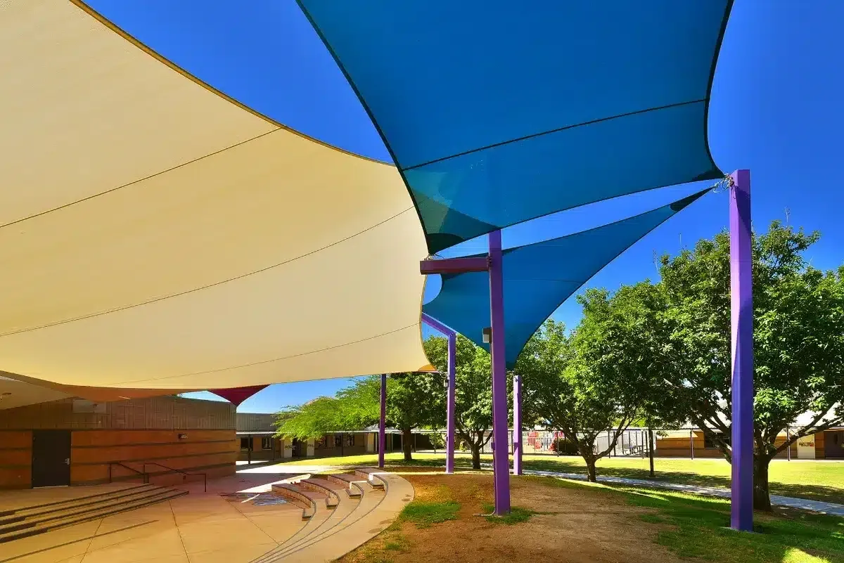
Arizona Shade Sails / Materials & structures
Plan the supports around the space: where posts can stand, where people need access and how the structure meets the ground or building. Fabric, steel, connections and foundations work together.
Project photograph / Coyote Trail / SHADE Industries
One connected system
Fabric tension and wind act on the entire shade system. The corner hardware transfers forces into posts or a reviewed building connection, then into foundations or the supporting building structure.
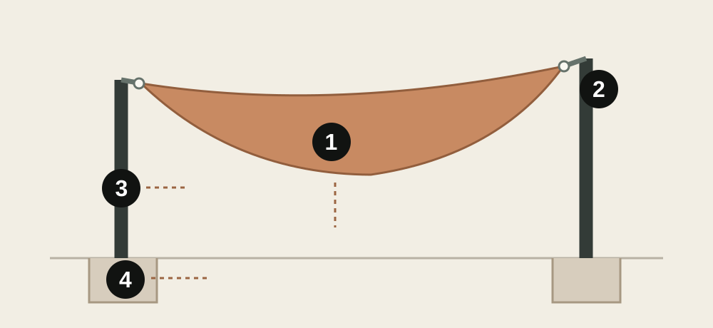
Start with the occupied area, clear routes and feasible attachment locations. The finished shade shape follows the support layout, rather than a fabric outline chosen without considering the site.
Request an EstimateLayout in the property
Freestanding posts keep the structure independent of nearby buildings. Building attachments can reduce the number of posts where the supporting structure and connection are suitable. Framed systems support panels or canopies within a defined arrangement.
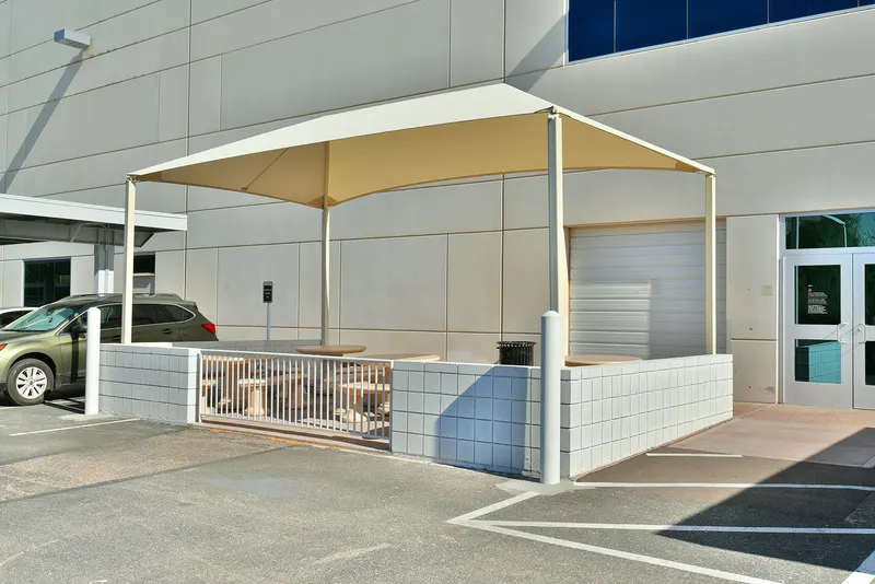
Supports stand independently of surrounding buildings. Allow for the post footprint, foundation locations and clear routes.
Project photograph / SHADE Industries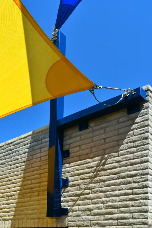
A connection can use an existing building where the supporting element and proposed attachment have been reviewed.
Project photograph / SHADE Industries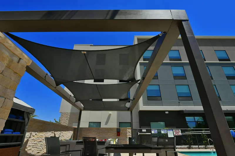
A frame defines the support arrangement for the fabric. Coordinate its footprint with circulation and the occupied area.
Project photograph / SHADE IndustriesCompare the footprint as well as the overhead coverage. Doors, vehicle movement, accessible routes, landscaping and service access affect where supports can go. The photographs illustrate layouts, not standard post or footing dimensions.
Browse project photographsFinish and exposure
SHADE Industries publishes in-house steel fabrication and coordination of powder coating or galvanizing where specified. The finish affects appearance, exposure protection and the maintenance plan, but it does not replace the structural specification.
A coating applied to prepared metal and cured to form the finish. Discuss the specified system, color reference, appearance and touch-up procedure.
A zinc coating on steel. Confirm the specified process, treatment of connections and any additional finish rather than choosing from a generic photograph.
Simplified layer illustrations, not steel color swatches or a promise of a particular finish appearance.
Discuss the exposure, desired appearance and care of connections as well as columns. Confirm surface preparation, specified finish, hardware and any site touch-up responsibilities in the written scope.
From layout to handover
The installation scope should connect the drawings to the finished property: layout, utility coordination, excavation, foundations, steel installation, fabric tensioning and surface restoration.
Establish the support locations, required clear routes and utility coordination before excavation.
Confirm access, excavation, reinforcement, concrete and required inspection responsibilities for the selected design.
Coordinate the fabricated supports, specified finish, anchors and connection details with the foundations or building.
Use the confirmed attachment points and specified fabrication details to fit and tension the custom sail or panel.
Agree who restores paving or landscaping and provides drawings, component records and care instructions.
Replacement and future changes
Bring original drawings and component records if they are available, plus photos of the supports, foundations, connection hardware and any visible damage. Condition and proposed loading determine whether an existing system can be reused.
Keep the confirmed drawings, finish and hardware information at handover. Later changes such as lighting, signage or additional fabric need review of their attachments and loads.
Clear answers
Sometimes. The supporting building element and the proposed connection both need review. The apparent size of a wall does not establish that it can take the sail’s forces.
No. The selected structure, loads, layout and site conditions determine the design. Generic online dimensions are not a substitute for project-specific engineering.
No. Powder coating adds a cured coating to prepared metal. Galvanizing provides a zinc coating to steel. Confirm the specified process and maintenance requirements for the project.
They may be suitable after assessment of their condition, foundations, connections and the proposed loads. A replacement fabric panel does not verify the old support system.